Electrical Installations
More about Electrical Installations
Electricians are needed wherever there is electricity. They can expect to work in homes, offices, factories, and even farms, carrying out maintenance and repairs, and sometimes designing and installing new systems.
Given the risks associated with electricity, offering a safe and reliable service to customers is paramount. Electricians need to have an intimate knowledge of the latest safety standards and work to a strict code of safety conduct.
Occupational Standard
The WorldSkills Occupational Standard specifies the knowledge, understanding and specific skills that underpin international best practice in technical and vocational performance. It should reflect a shared global understanding of what the associated work role(s) or occupation(s) represent for industry and business.

Definition of Electrical installations
Electrical installations means the construction or installation of electrical wiring and the permanent attachment or installation of electrical products in or on any structure that is not itself an electrical product. “Electrical installation” also means the maintenance or repair of installed electrical wiring and permanently attached electrical products. “Electrical installation” does not include an oil module.
Examples of Electrical installations in a sentence
Electrical installations and repairs involving communication and signal systems of railroad companies.
Electrical installations and repairs involving remote and permanent broadcast systems of radio and television stations li- censed by the Federal Communications Com- mission if the systems are not part of the building’s permanent wiring.
Electrical installations inspection and maintenance
How To Wire Switches In Series?
How to Connect Two Switches in Series to Control a Single Load?
In today basic home electrical wiring installation tutorial, we will learn how to wire and connect two switches in series to control and operate a single light point.
Mostly, this is not a proffered method to wire single way switches in series as parallel or series-parallel connection is used in common electrical wiring installation. In some case, it may seems useless connection, but there are some possibilities where we have to control single load from two places while both switches must be switch ON to operate the load
Below is a simple step by step tutorial with schematic and wiring diagram which shows how to wire single way switches in series ?
Requirements:
Single Way Switches (SPST = Single Pole Single Through) x 2 No
Lamp (Light Bulb) x 1 No
Short pieces of cables x 4 No
Procedure:
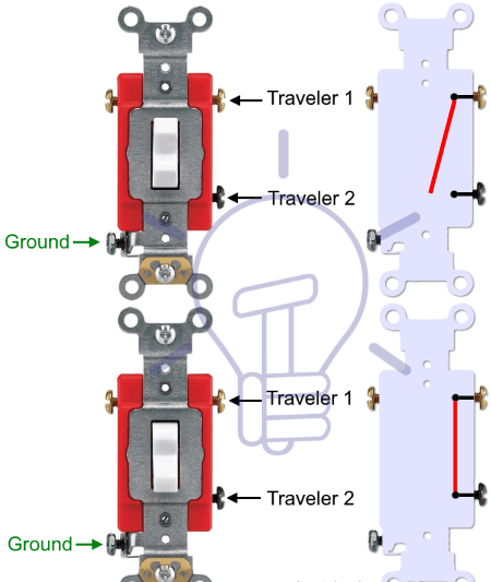
Connect the two single way switches, light bulb in series to the power supply as shown in fig below. Keep in mind that both switches S1 and S2 must be closed to complete the circuit. If there are more switches connected in series with electrical appliance i.e. light point, all of them must be at ON position to operate the load. If one of the single switch is open, the circuit won’t work then.
The circuit will only complete if both of the switches are at ON position. In other words, If one of the switch are open or at OFF position, the light bulb will not glow. This is the same case for other loads as well which are connected in series to control by two single way switches.
In simple words, there are four switching positions and if both the switches are at ON position, the light bulb will glow. On the other hand, if one of the switch is at OFF position, the current will not flow in the circuit as the circuit behaves like an open circuit, hence bulb will not glow. No matter all of other connected switches are at OFF or ON positions.
Electrical Installation
Electrical Installation is easy to handle and is fully integrated with other disciplines such as electrical engineering or cabinet engineering. You can design power distributions in buildings and define the location of operating material in machines, plants and buildings. Existing floor plans in PDF or DWG format are imported to scale
All field devices from the plant layout and control diagrams (from Building Automation design) are placed in the floor plans and linked to the existing symbol data of the diagrams. Cable labels are taken over, cable and material lists are generated, and the software automatically calculates all required material quantities. This makes your project work much easier and eliminates time-consuming calculations for quotations.
Electrical Installation is ideal for engineers, electrical installers, craftsmen companies, facility managers, electrical system contractors and cabinet builders, as well as maintenance and service personnel specialised in electrical and building technology.
Deal with shortage of skilled personnel and an ageing workforce
Securely save employee knowledge in project templates including the right parts data. Once an employee leaves their know-how is still available within the company.
Easy-to-Use: amongst other prices software has been awarded with the „Golden e“for its easy to use user interface.
Access over 1.4 million parts data and symbols from more than 280 manufacturers in wscaduniverse.com and save yourself the hassle of designing the parts.
Use one single software to handle different aspects of a building of plant: network plan, circuit diagram, hydraulic/pneumatics, piping and instrumentation diagram, cabinet engineering, etc.
Handle the cost pressure
Use your human brain power where it is irreplaceable and let software handle other tasks
Reduce manual work by automating engineering processes and store your know-how in standard project templates. Reusing these saves enourmous amonunts of time and substantially improves the quality of your output.
Gather data only once and then access it seamlessly across all engineering disciplines: from the data point of a sensor to the terminal in the cabinet. Make use of the integration to PLM and ERP systems to integrate all engineering data in one backbone. It reduces errors and rework.
Finish engineering projects faster
With you can create installation und distribution plans for 140 residential units in 1.5 days, including all documentation. Just ask us for real life examples.
Use product configurators to generate schematics
Define standards and increase reuse of standard modules to save enourmous amounts of time while achieving higher quality at the same time.
Rely on the integrated dictionary to create multi lingual schematics.
How To Wire Switches in Parallel?
How to Connect Two Switches in Parallel to Control a Single Load?
In previous basic home electrical wiring installation tutorial, we learned how to wire single way switches in series. Today, we will learn how to wire and connect two switches in parallel to control and operate a single light point.
Mostly, this is a preferred method to wire single way switches in parallel as parallel or series-parallel connections are used in common electrical wiring installation these days due to advantages over series connection
Below is a simple step by step tutorial with schematic and wiring diagram which shows how to wire single way switches in parallel?
Related Wiring Tutorials:
Godown Wiring Diagram – Tunnel Wiring Circuit and Working
Tunnel Wiring Circuit Diagram for Light Control using Switches
Requirements:
Single Way Switches (SPST = Single Pole Single Through) x 2 No
Lamp (Light Bulb) x 1 No
Short pieces of cables x 5 No
Procedure:
Connect the two single way switches, light bulb in parallel to the power supply as shown in fig below. Keep in mind that one of the switches S1 or S2 must be closed to complete the circuit.